NASA Contractor Report 187169 AIAA-91-2208
Plug Nozzles – The Ultimate Customer Driven Propulsion System
Carl A. Aukerman
Sverdrup Technology, Inc. Lewis Research Center Group Brook Park, Ohio
August 1991
Prepared for Lewis Research Center
Under Contract NAS3 – 25266
PLUG NOZZLES – THE ULTIMATE CUSTOMER DRIVEN PROPULSION SYSTEM
Carl A. Aukerman, Senior Propulsion Specialist, Member AIAA
Sverdrup Technology, Inc
NASA Lewis Research Center Group Brook Park, Ohio 44142
ABSTRACT
This paper presents the results of a study applying the plug cluster nozzle concept to the propulsion system for a typical lunar excursion vehicle. Primary attention for the design criteria is given to user defined factors such as reliability, low volume, and ease of propulsion system development. Total thrust and specific impulse are held constant in the study while other parameters are explored to minimize the design chamber pressure. A brief history of the plug nozzle concept is included to point out the advanced level of technology of the concept and the feasibility of exploiting the variables considered in the study. The plug cluster concept looks very promising as a candidate for consideration for the ultimate customer driven propulsion system.
INTRODUCTION
The next generation of space propulsion systems to be used for manned exploration of the moon and Mars will present unusual challenges for the aerospace community· Clearly there are very high performance demands especially for Mars, but there will also be an extreme requirement for high reliability and minimum total program costs. The enormous total program commitment will undoubtedly force the mission reliability and overall costs to be dominant in decisions at all levels throughout the design, development, manufacturing, qualification, preparation, and operational phases of the program. The very existence of the program may depend on the industry’s ability to convince the program sponsors, the Administration and the Congress, of our ability to achieve the necessary product reliability at a predictable, reasonable cost. Recognizing the historical trends in cost and reliability, the industry can not afford to meet the new program demands unless there is a “better, smarter” way of providing space propulsion systems. Some important space exploration opportunities will have to be limited or even abandoned without those “better, smarter” ways of providing cost effective, reliable propulsion systems to do the job.
In simplified terms, the challenge for future propulsion systems can be reduced to three objectives:
- to provide for extremely high mission reliability,
- to package a high performance system in a small volume, and
- to design a system that minimizes schedule and costs.
High mission reliability is really the fundamental requirement for a system to meet those unquantifiable factors such as man rating, re-usability, fault tolerance, and s ace basing. Concepts such as redundancy, engine out, and fail safe/fail operational are really subsystem approaches to meet an overall mission reliability requirement. In the past, the mission reliability requirement has frequently been viewed as an extreme requirement for each subsystems with minimum options for alternate system configuring to achieve success.
The packaging issue recognizes that the volume available for upper stages is usually critical. First the stage must fit inside a shroud or payload bay of limited size. Components such as bell nozzles force severe volume, weight, and complexity problems on a deployed upper stage designed in the traditional manner. The design approach of simply extending the nozzle to an area ratio high enough to meet a performance target imposes severe penalties to an upper stage. This cascades, for example, into excess interstage structure, complicated nozzle extension mechanisms, extra long landing legs, and payload unloading problems on the planetary surface; all very penalizing to the mission objectives.
The final challenge, relating to development schedules.and costs, recognizes that proposed high pressure.· systems are rather unforgiving, difficult to develop, and expensive to maintain. In addition, high area ratio nozzles are typically part of the engine cycle balance and must be tested as a complete unit. This requires that extensive development and qualification testing be done in expensive altitude facilities.
The objective of this paper is to briefly review the history of plug nozzles and plug cluster nozzles, to point out some unique features, and to explore some of the options to show that a different methodology to propulsion system design can offer relatively easy, low risk solutions to meeting the future needs of space propulsion.
To exploit this design approach, a specific configuration of a propulsion system for a lunar landing vehicle will be proposed using a total propulsion system methodology. The baseline vehicle was extracted from ongoing studies in the Space Exploration Initiative (SEI) program. The resultant design features are discussed in terms of meeting the ultimate user needs of high mission reliability, high performance, minimum volume, and design features leading to minimizing schedule and costs.
The argument thus developed should provide a process to show that the plug cluster concept can truly be the ultimate customer driven propulsion system.
PLUG NOZZLE HISTORY
The plug nozzle is the fundamental configuration for obtaining thrust from a free or unconfined expanding supersonic jet stream. Application of this phenomena to rocket propulsion was conceived in the mid 1940’s. Over 25 patents involving the various configurations and applications of plug nozzles were uncovered during the course of this work. It appears that the first direct application of the plug nozzle to a rocket propulsion application was described in a U.S. patent filed in 1950 by A.A. Griffith of Rolls Royce Limited (ref. 1). During the 1950’s a great deal of evolutionary and developmental work was done by the General Electric Company (GE) under the leadership of Dr. Kurt Berman and Dr. A.R. Graham. That work culminated in the hot firing of a 50,000 pound thrust plug nozzle rocket engine.
Reference 2, “Plug Nozzle Handbook”, describes the activities leading to that firing and is of considerable historical and educational significance since it documents and references much of the early work conducted in the 1950’s at General Electric. It is one of the very few references dedicated entirely to a detailed.discussion of the theory of external expanding nozzles and their design, complete with an excellent reference list, as compiled by some of the plug nozzle pioneers. A photo of that large scale plug nozzle hot firing, figure 1, was taken from that source.
Since that early work, funding from NASA, the USAF, and industry internal sources have been used to compile a tremendous data base of analytical and experimental knowledge on many variations of the plug nozzle concept. Aerojet, Rocketdyne, and Pratt & Whitney have all made important contributions in the recent years since GE’s initial results. The most recent activity completed in 1976, prior to the current SDIO work, resulted in the 15,000 pound aerospike thrust device shown in figure 2. This design, supported by the USAF (ref. 3), was for an advanced, high performance, maneuvering vehicle. Clearly, the plug nozzle rocket engine. it’s not a new idea, nor is it unexplored technology.
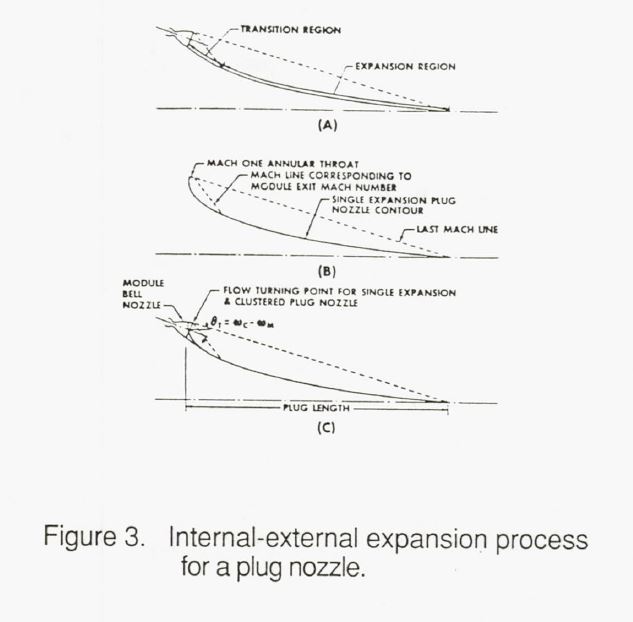
The concept is known by various names e.g. external expanding nozzle, plug nozzle, aerospike, pen shaped, or integrated modular engine. In its most fundamental form the external expanding nozzle is based on the Prandtl-Merer corner expansion wave theory originally developed in 1908 (ref. 3). This theory, depicted in figure 3a, describes the behavior of an unconfined supersonic stream expanding into a lower pressure environment. A photograph found in reference 3 shows a Schlieren image of supersonic corner expansion first filmed by Prandtl in 1908. The process is one where expansion of a supersonic stream around a corner continues until the static pressure of the supersonic stream reaches the static pressure of the surrounding ambient conditions.
The theory applied to a propulsive plug nozzle design results in a concept depicted in figure 3b. By tilting the axis of the primary flow stream, the exhaust gases expand into a completely axial supersonic stream, thereby producing the maximum velocity and thrust in the axial direction.
Many variations of this fundamental concept are possible, each having advantages and disadvantages. Many of these variations have been explored using excellent analytical codes. Classical supersonic flow analysis predicts two dimensional and axisymmetric external expanding nozzle flow characteristics very well and has served as an excellent starting point for the numerous variations employed, especially for the annular flow geometry. This analysis has been supported by extensive cold flow experimental data obtained with reduced scale hardware. si9nificant cold flow testing has also been conducted on variations that are difficult to rigorously model analytically, such as truncated center bodies, discreet throats, and off design operation.
Several full scale, hot fired demonstrations have also been performed ranging from 15,000 pounds of thrust to 250,000 pounds of thrust. A conventional annular lug nozzle and a linear version of the plug nozzle were designed and tested at 250,000 pounds thrust by Rocketdyne in the mid 1960’s. In virtually all cases, the analysis predicts both the small scale cold flow experiments and the full scale hot fired tests rather well. Properly designed plug nozzles can attain very high performance efficiency; nominally equivalent to conventional contoured bell nozzles.
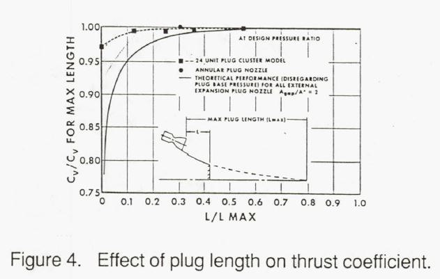
One of the unique aspects of a plug nozzle design is the method of controlling the expansion process. If designed properly, the outside streamline of the flow field will be essentially an axial profile controlled by the ambient pressure and Prandtl-Meyer characteristics. To achieve this axial flow, the modules controlling the internal expansion are “tilted” inward at the proper angle. The Prandtl-Meyer expansion remaining at the exit of the internal expansion expands or turns to the axial direction under the control of the plug contour, designed by conventional method-of characteristics methods to produce shock free expansion and turning. Thus the control of the expansion by the lug is on the inside of the flow field as opposed to the outside of the flow field as in the case of a conventional bell nozzle. In a vacuum, the resulting exhaust is a fully developed flow field and the expansion surface has no way of communicating with the ambient surroundings. As a result, some liberties can be taken with the design of the plug. one of the most useful features is to truncate the plug and allow internally recirculated gases to pressurize the captured base region. Experiments have shown that this truncation can be done with minimum of performance loss. Figure 4 (ref. 5) shows a set of typical cold flow data that shows the effect of plug truncation. Note that the plug can be truncated to about 20% of its isentropic length with a minimum of performance loss.
The advantage of this unique characteristic of plug nozzles is that truncation of the plug permits the length of a high area ratio propulsion system to be greatly reduced with a minimum of performance penalty. Typically designers use conic section or bell nozzles that are extremely long when high area ratio is required for maximum performance. Since the plug nozzle can be truncated to about 20%, this allows the designer to avoid many integration problems associated with the extremely long conventional bell nozzles; problems such as long interstage structures, long landing legs, large flimsy nozzle extensions, and high elevation platforms to unload the stage on the lunar surface.
There are two distinct applications for external expanding nozzles:
(1) for first stage vehicles, where the external expansion allows an increase in effective area ratio as the vehicle moves up through the atmosphere; commonly referred to as “altitude compensation”, and
(2) for space vehicles, where the vacuum environment allows a truncation of the ideal isentropic plug contour to a very short length with a minimum of performance effect.
This paper limits the discussion to the latter application.
As a closing comment to this historical discussion, three excellent references exist that have compiled a listing of most of the available material on external expanding or plug nozzles. The early work by General Electric is nicely summarized into a virtual textbook in reference 2. Reference 6, which is discussed in more detail later, summarizes a broader ran e of industry activities, providing highlights, data, and discussion on the major experimental efforts. A compendium was commissioned by the USAF in the mid 80’s and documented in reference 7. And very recently, a technical development summary was funded by the Marshall Space Flight Center, reference 8. This last reference is a concise, compendium but with limited data included.
REFERENCE BASELINE VEHICLE
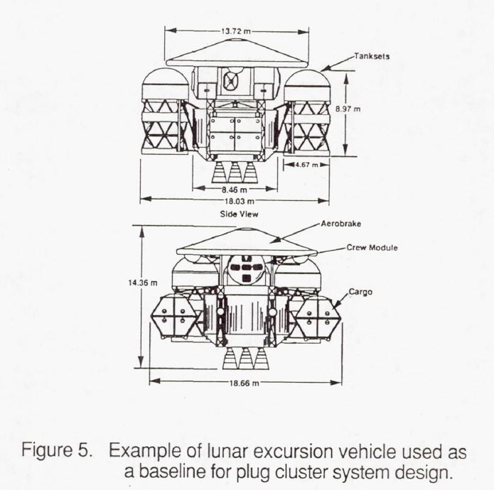
To explore a plug cluster nozzle design methodology, a reference or baseline vehicle was selected. For the purposes of this thesis, a lunar excursion vehicle was selected from those presented by contractors conducting the studies for the Space Exploration Initiative (SEI). The vehicle selected is the preferred configuration in the Martin Marietta corp. study, described in reference 9 and shown in figure 5.
A summary of the mission requirements for this vehicle is reproduced in Table 1. The purpose of this selection process was to work with the results of a study that has a great deal of thought and analysis leading to the vehicle description.
Later examples will refer to the details of this baseline configuration.
Table 1 Assumed Vehicle Requirements
Total Vehicle Thrust: 80,000 pounds
Vehicle Core Diameter: 27.5 ft (8.46 M)
Throttling Range: 10:1
Length: 88 inches scaled
Chamber Pressure: Vehicle/Mission Variable
Mixture Ratio: Vehicle/Mission Variable
TYPICAL NOZZLE DESIGN TECHNIQUES & TRADEOFFS
This section describes a preliminary design process involving a cluster of engines around an external expanding nozzle, i.e. a plug cluster. The objective of this process is to attempt to simultaneously meet the user needs of:
- high mission reliability,
- high performance in a minimum volume, and
- a propulsion system that can be confidently developed on schedule and within the cost restraints.
High mission reliability can be achieved through a propulsion system that:
- reduces the likelihood of failed components, and/or
- continues to perform even if individual components fail.
If this philosophy prevails for the system, a variety of non-traditional design opportunities can be considered to achieve the desired end.
For example, the probabilities of component failures tend to be proportional to the severity of the imposed loads. If loads can be maintained well within established technology ranges and flight demonstration limits, the component failures can be expected to be minimized. In this case, the imposed loads are parameters such as chamber pressure, chamber heat transfer rates, pump pressures, and turbomachinery speeds. Most of the failures, or schedule delays for maintenance, in high performance propulsion systems can be traced, directly or indirectly to high values of these loads and the design features employed. When these loads can be minimized, a wider range and lower cost of materials and fabrication techniques become available. All of these loads can be minimized by keeping chamber pressure as low as possible.
With the plug cluster layout, the total thrust requirement of the vehicle can be satisfied at lower chamber pressures than conventional configurations. The advantage comes in utilizing the full diameter of the vehicle for the propulsion system to distribute the total necessary total throat area.
Individual round discrete throats provide a distribution of flow and thrust with very reasonable dimensions. This technique then becomes a primary variable for achieving the goal of the design process.
The design procedure discussed is keyed to the baseline vehicle description from the SEI program. For various vehicle and mission reasons, the total thrust of the propulsion system is generally focused on a desired range; 80,000 pounds in this example. To efficiently provide the required energy, the design process usually trades vehicle mass fraction, propellant mixture ratio, and the highest expected value of specific impulse from the propellant combination. For this. study, both of these parameters, total thrust and specific impulse (at the design mixture ratio) were fixed as subsystem requirements for all configurations. As a first order generalization, specific impulse was assumed to be a direct function of available area ratio for supersonic expansion.
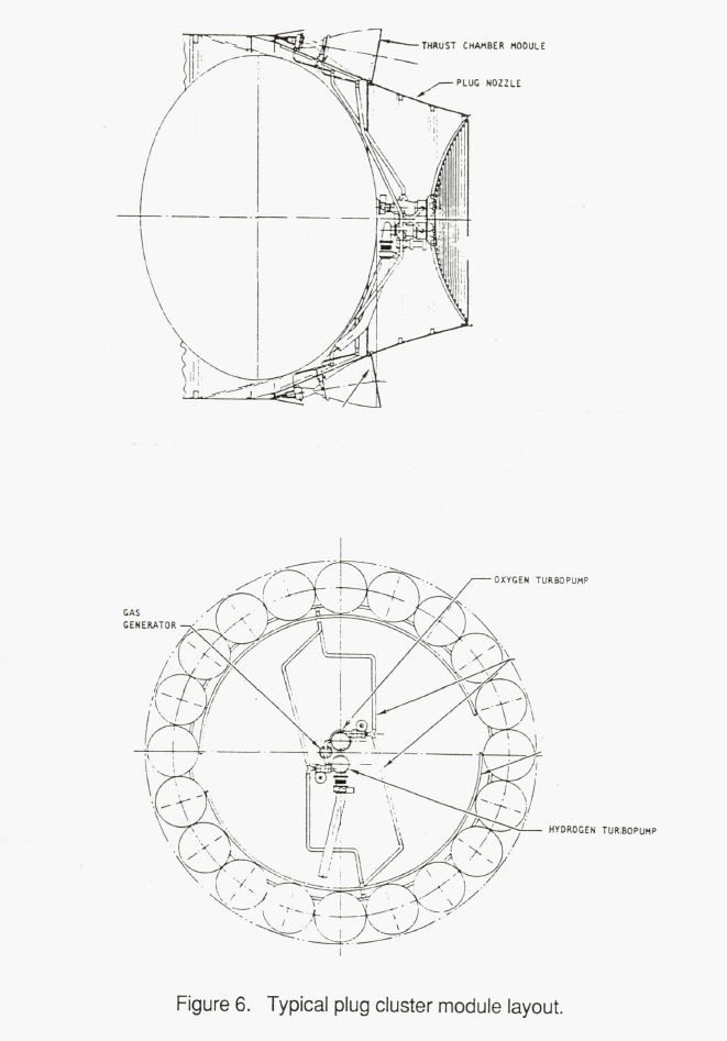
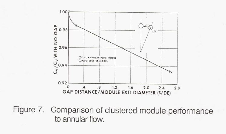
The design configuration evaluated is one where the thrust devices or modules are arranged around the circumference of the plug with axisymmetric bell nozzle exits that touch in a nearly annular geometry. Figure 6 shows an example of this arrangement. The full expansion process continues from these module exits onto the surface of the plug or it’s truncated equivalent to the full area ratio. To maximize performance, it is useful to have the module exits touch, which tends to simulate annular flow. Figure 7 from reference 5 shows that
The performance trend is virtually identical to that of an annular plug when the module exits touch. In this configuration, the function of the supersonic internal expansion of the modules is to e and the gases and direct them into a nearly annular flow field onto the plug contoured surface at the correct angle. The internal or module area ratio, contour, and length that is required to perform this flow field control is not.important except for the weight of the module nozzle surface. The system performance is ultimately determined by the overall area ratio. A module configuration similar to figure 7 can be laid out with total thrust, area ratio, and maximum diameter determined by the vehicle studies. In the case of the plug cluster design, overall area ratio is:
(1) E= (ADv) / (At*N)
where:
- AR = the overall or vehicle area ratio
- N = number of modules
- At = module throat area
Recognizing that total thrust is
(2) F=N*Pc*At*Ct
where:
- Pc= chamber pressure
- Cf= nozzle thrust coefficient
and for an ideal gas,
(3) Cf = f(E, γ)
Using these equations, the geometry of the touching circular modular exits, and the vehicle inputs mentioned earlier, an expression can be developed that relates required chamber pressure to the number of modules. That resulting relationship to conduct design parametrics is:
(4) Pc = (1/N) * (1/At) * (F/ ήCf) * (1 / (Cf = f(Pc/Px, Adv/At, 1/N))
where:
Pc/Px = nozzle pressure ratio
- Dv = vehicle diameter
This expression produces a family of viable propulsion system meets all the input requirements.
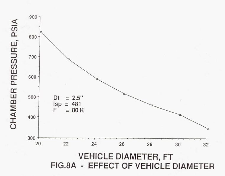
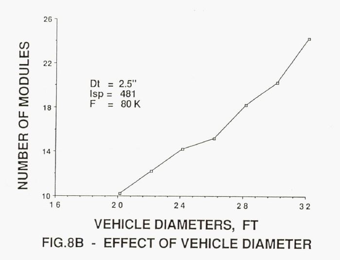
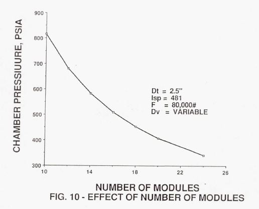
A sample of the tradeoff resulting from equation (4) is shown in figure a through 10. Figure 8 shows three different impacts of utilizing the vehicle or propulsion system diameter as a design variable. Figure Sa shows that a very large reduction in module chamber pressure is possible by increasing the diameter of the installed cluster of modules. The resulting increase in the number of modules is shown in figure 5b. In figure 5c, the results of a slightly different trade shows the specific impulse that would be sacrificed if some specific design chamber pressure were desirable. This case might be useful if the design were to consider existing hardware for the modules.
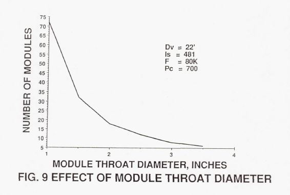
The throat diameter of the modules was considered as a design variable in figure 9. Although small modules offer the possibility of very high area ratio, the total thrust requirement dictates a very large number of modules is required. Of course, larger throat diameters approach the conventional axial bell nozzle configuration.
The final summarization of this parametric trade study is presented in figure 10. An arbitrary throat diameter of 2.5 inches was selected to determine how low the chamber pressure could be reduced by increasing the number of modules. This figure is a cross plot of figures 5a and 8b. It appears that a reasonable configuration results when 16 modules, operating at about 510 psia chamber pressure are selected. This pressure level is well within the range of demonstrated technology, and the configuration can produce the necessary specific impulse of 480 seconds. Advanced concepts or advanced materials are not necessary to meet the system performance requirements.
A generalization of this trade study is that the curves tend to flatten out to a minimum chamber pressure for very large numbers of modules. The vehicle diameter was clearly the most sensitive parameter to exploit for this concept.
Pressures as low as 300 psia are possible for vehicles up to 32 feet in diameter. Some of the vehicles in the SEI studies could accommodate propulsion systems of that geometry.
The ultimate decision on module size and number would undoubtedly be determined by other factors, such as cycle design, chamber cooling, turbomachinery speeds and pressures, manufacturing o tions, operational efficiency, and propulsion system reliability. Reference 5 looked into many of these factors and determined that several different engine cycles could be used.
POTENTIAL APPLICATION AND CONFIGURATION
Performance Impact
The results of this parametric configuration study provide a basic building block for a propulsion system that could be considered for a lunar excursion vehicle typical of the SEI program. Using the data from this study, an arbitrary configuration was selected for further evaluation; highlights of that configuration are reproduced in Table 2.
Table 2
Total System Thrust            80,000 Pounds
System Area Ratio              974:1
System Specific Impulse        481 Seconds
Vehicle Base Diameter          26 Feet
Number of Modules              16
Module Chamber Pressure        509 PSIA
Module Thrust                  5,000 Pounds
Module Area Ratio              420:1
Module Throat Diameter         2.5 Inches
Module Exit Diameter           51 Inches
Module Length                  94 Inches
Plug Length, Additional        36 Inches
Total Plug Cluster System      130 Inches
Typical Bell Engine Length     196 Inches
System Length Reduction        66 Inches minimum
With this selected configuration, a propulsion system could be designed to meet the mission requirements at 500 psia chamber engine and 5000 pounds thrust; i.e. flight demonstrated technology with 30 years of experience.
Mission Reliability Impact
Thus far the only aspect of the three original requirements described in the Introduction that has been discussed is that a high performance propulsion system can be packaged into a minimum volume or length. The second desirable requirement for the lunar excursion vehicle (LEV) relates to high mission reliability.
Certainly the relatively benign environment of a 500 psia chamber pressure system should be a dominant factor in attaining high reliability for the components of this system. However, the system reliability is greatly enhanced by the options inherent in a modular assembled propulsion system.
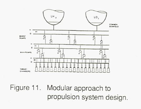
Modularity has been studied in-depth by Rocketdyne under KSC contract, reference 10, for the purpose of operationally efficient propulsion systems. Escher, in reference 11, has also extolled the advantages available from such packaging. Figure 11 is taken from Escher’s treatise as an example of how the system could be assembled for maximum mission reliability.
The premise in the modular arrangement is that each individual component interacts only with a manifold or plenum and not with the dynamics of other components. Should an individual component malfunction, only that component shut down and operating components are never shut down. is different from the conventional approach where whole “engines”, including operating components, are shut down the first sign of a problem. With manifold isolation, a malfunctioning component eliminated from the system does interact with any other component, and the remaining components in the system continue to operate undisturbed.
As an example, six turbopumps might be used to feed the fuel manifold for the entire propulsion system including 16 thrusters. Should one fuel turbopump fail, the thrust chambers would never be aware of the failure because the remaining pumps, operating at 20% over the design point could easily make up the required flow. Off design operation to this extent has often been demonstrated for cryogenic turbomachinery and is highly developed technology. This option is not available with the system designed in the conventional fashion.
As a highlight of this arrangement, the propulsion system could experience and shutdown a malfunctioning:
- fuel boost pump, oxidizer boost pump,
- primary fuel pump,
- primary oxidizer pump, and
- a pair of thrust modules
…AND STILL COMPLETE THE MISSION – a highly desirable situation that is not attainable with a conventional “engine”.
Should one of the thruster modules experience a malfunction and require shutdown, .several options are possible. The most direct option is to shut down a good thruster 180 degrees away in order to continue to balance the thrust vector.
That entails a minimum performance loss from the gap created and may require some protection of the unused thruster from hot exhaust gas recirculation. If the thrust per module is relatively low, a thrust vector correction could be employed by gimbaling an opposite engine, gimbaling the entire plug-cluster, or putting the load into the thrust vector control system which might even use additional units of the primary modules.
·In the case of landing, throttling is frequently defined as a firm requirement, sometimes as high as 20:1. This is a severe requirement for a single “en ine” and complicates the system design to insure stable conditions over the entire range. With a cluster of thrusters, individual or paired units could be shut down or even throttled slightly to achieve 20:1 well within established technology.
Certainly this arrangement would require addition lines and numerous valves. However, the line sizes would be less than 111 in diameter. Isolation valves would be required for each component for use in case of a malfunction. Valves for 1″ flow systems are generally very simple, reliable, and much lower in cost, proportionally, than a conventional large single valve.
Probably the most challenging en9ineering problem of this configuration would be dealing with the flow system dynamics to ensure that the manifolds did indeed act as plenums of constant characteristics.
Development Impacts
Chamber Pressure Effects – The final challenge, relating to development schedules and costs, recognizes that proposed high pressure systems are rather unforgiving, difficult to develop, and expensive to maintain. With most of the high pressure engine designs, the state-of-the-art is being pushed forward with temperatures, chamber cooling, pump speeds, bearing loads, rotor dynamics, seals, materials, and fabrication techniques. In many instances, near perfection is required in design, fabrication, inspection, and operation. That is needless development risk to schedule, cost, and mission when a different design ap roach results in more benign environments. The development risk in schedule, certainty, and cost for small, low pressure, state-of-the-art components is much smaller than any advanced technology approach operating at 2000 psia. The plug cluster configuration offers a more benign environment of 500 psia chamber pressure to produce the desired 480 seconds of impulse.
Modularity Effects – A very strong advantage of an assembled propulsion system like the modular approach is the opportunity to do virtually all the development of the components on a component rig since the manifolds isolate the system. This would be particularly advantageous for the thrust modules. Should the industry develop a 20,000 pound thrust engine with a nozzle of area ratio 1000:1, there are very few facilities in the country that could be used for testing. The modular approach described herein could be developed at the component level in numerous facilities around the country, or even in sea level facilities, depending on the cycle selected.
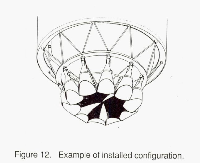
Operational Efficiency – One final advantage of the configuration described is that it can be designed to be an operationally efficient propulsion system. The configuration offers many opportunities to minimize the checkout and maintenance requirements necessary for all systems. The use of the full base of the vehicle inside of the plug nozzle allows an arrangement of the components in an easily accessible configuration. The volume inside the plug nozzle compartment can be open to ease the impact of leaks.
Although this configuration contains a large number of pieces, there are many identical ones, thereby minimizing spares, and checkout procedures. The components are comparatively very small in size which eases handling. These small components would also be proportionately much lower in cost than their counterparts in a full size engine.
CONCLUDING REMARKS
This report presents a methodology for the design of a propulsion system that would meet the ultimate user needs of high performance, minimum volume, high mission reliability, and design features leading to minimizing schedule & costs. A cluster of individual modules around an external expansion plug nozzle offers a design approach that meets those needs.
To explore this design approach, a specific configuration of a propulsion system was described for a baseline lunar excursion vehicle selected from ongoing studies in the Space Exploration Initiative program. The resultant design features were shown to meet those user needs. The resulting propulsion system configuration consisted of 16 modules clustered around a plug nozzle on the base of a 26 foot diameter vehicle. The system, operating at only 500 psia chamber pressure, achieves a specific impulse 480 seconds in an engine length over 5 feet shorter than a conventional bell nozzle configuration.
By designing the components of the feed system into modular arrangements separated by manifolds, the ultimate system can tolerate multiple component malfunctions and virtually assure mission success.
The modular component and manifold system approach allows the individual components to be carried to a high degree of development without coupling to the complete system, where testing costs are extremely high. The system supporting a chamber pressure of only 500 psia involves very low risk, well established technology that not only leads to high operational reliability, but also reduces development difficulty – namely schedule and cost.
The plug cluster propulsion system concept seems to offer a tremendous opportunity for an ideal space propulsion system that can truly be the ultimate customer driven propulsion system.
REFERENCE.S
- A.A. Griffith, Jet Propulsion Nozzle for Use at Supersonic Jet Velocities, Patent Number 2,683,962, Rolls-Royce Limited, July 20, 1954.
- Graham, Dr A.R., Plug Nozzle Handbook, General Electric Company, Contract NAS9-3748, August 1965.
- Advanced Maneuvering Propulsion System Program. Contract No. AF04(611) -11617/F04611-67-C-0ll6, June, 1970.
- Anderson, John D. Jr., Modern Compressible Flow With Historical Perspective., McGraw-Hill Book Company, 1982.
- Study for the Evaluation of Plug Multichamber Configuration, PWA FR-1415, Pratt & Whitney Aircraft, October 1965.
- O’Brien, C.J., Unconventional Nozzle Tradeoff Study, CR-15952O, Aerojet Liquid Rocket Company, July 1979.
- Sutor, A.T., Rocket Engine Nozzle Compendium, Contract F33657-82-C-0346, Rocketdyne Division, 1985
- Ballard, R.o., The Aerospike/Aeroplug Engine, Contract – NASS-37814, Sverdrup Technology, Inc., 1991.
- Space Transfer Vehicle Concepts Requirements study, Interim Review 5, Contract NASS-37856, Martin Marietta, Corp, SEI studies., January 1991.
- Operationally Efficient Propulsion System study, Contract NASl0-11568, Rocketdyne Division, 1990.
- Escher,· W.J.D., NASA Headquarters, Personnel communication, 1991.
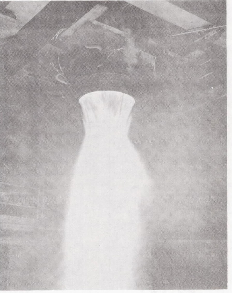
Figure 1. Test firing of a GE plug nozzle at 50,000 pounds thrust in 1959.
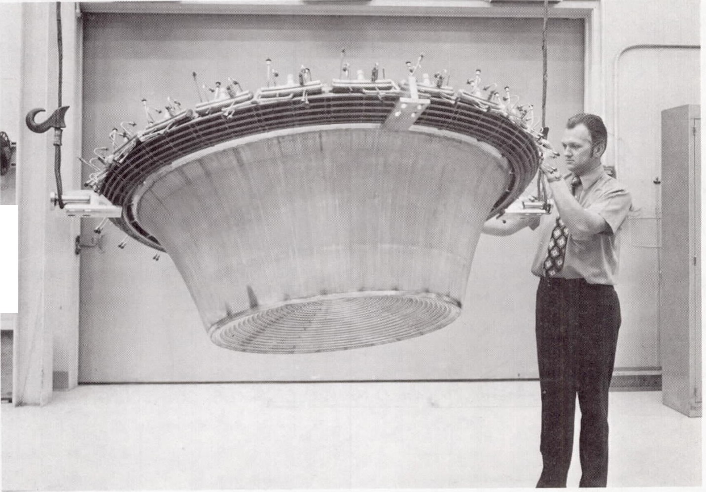
Figure 2. Flight type aerospike nozzle designed for 15 ,000 pounds thrust.